The other day I was surfing the web, trying to avoid doing anything productive, and I came across a neat little antique New York style mule ear rifle. What I found interesting was that the rifle was very similar in appearance to an antique rifle that I purchased a few years back, with the exception that mine has an A.W. Spies sidehammer on it. I always found the lines of this particular rifle appealing, but never went any further with it until I saw this mule ear. I started imagining what the original builder would have done if a customer had wanted a mule ear style rifle. I figured I would keep the basic elements the same and concentrate on building a lock that would fit the rest of the rifle, so off to the shop I went where I spent the better part of the afternoon avoiding the house chores that needed to be done. I figured some of your might like to see the progress on this project so I took a few pictures along the way.
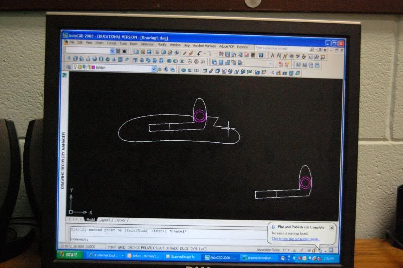
I started by tracing the original A.W. Spies lockplate on a piece of paper, scanning the image and importing it into AutoCAD where I played around with the location of the slot where the hammer will eventually go. I basically wanted to retain the original shape of the plate, but there are some significant changes to go to this style of lock. I started by grabbing a chunk of 3/8" (1/4" would have been better but I didn't have any) hot rolled steel and tracing the outline of the plate onto the end of the bar. The extra length of the bar gave me something to hold onto while I was cutting out the profile on the vertical bandsaw.

You could certainly use a hacksaw for this, but being essentially a lazy sort of person and having the technology I chose the easy route. You can see from the side view that there is a lot of material to remove.
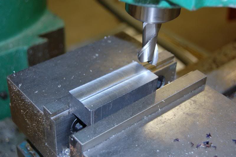
The rough blank was mounted into the vise of the mill and one side was surfaced.
With one face cleaned up a line was scribed into the edge at .207 and the other side was milled down to the line.

I than transferred the blank to the surface grinder where I ground both faces down to .195. This step wasn't really all that necessary, but I had the grinder available and it only took a couple of minutes to do.
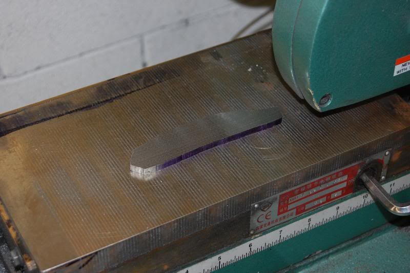
And finish ground
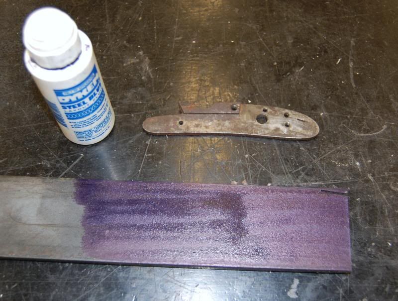
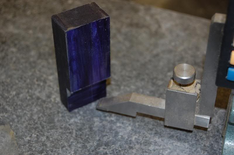
Following this the guidelines for the plate were re-traced using layout dye and the original plate as a template. I C-clamped it in place using a copper shim to protect the original.
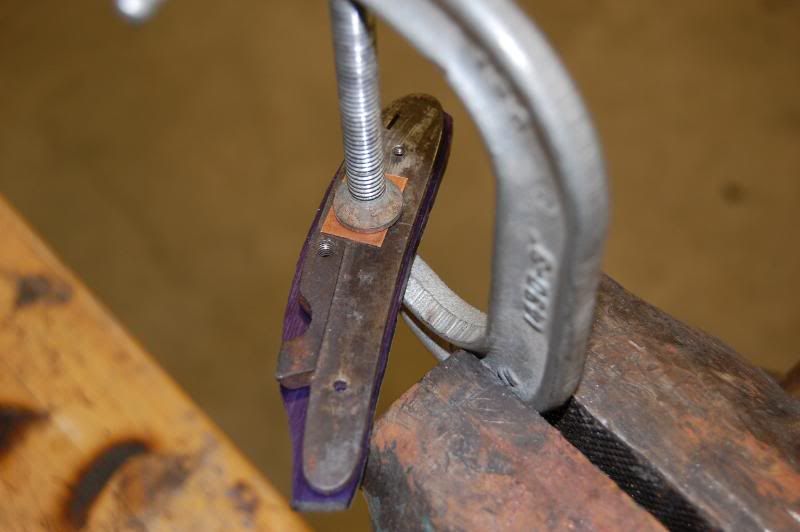
The new layout lines can be seen in the photo below.

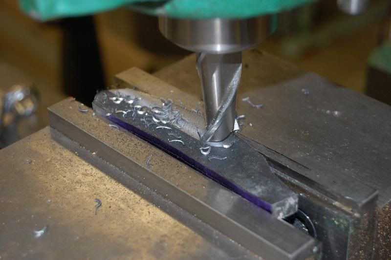
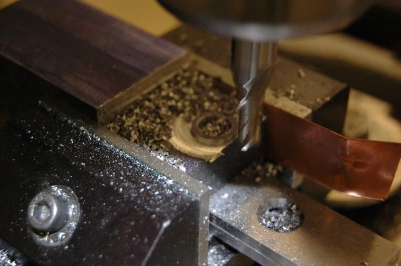
I felt it was best to cut the slot for the hammer next while the plate was still in the rough form. I chose to go this route since I didn't want to mash the edges of the finished plate in the mill. The slot was layed out using a print of the CAD drawing I created and scribed onto the blank using the boundry lines that were scribed onto the plate earlier. Since the slot does not run parallel to the edges of the plate I used a rotary table another mill to line up the slot parallel to the mills travel and adjusted it using an edge finder until I was satisfied.

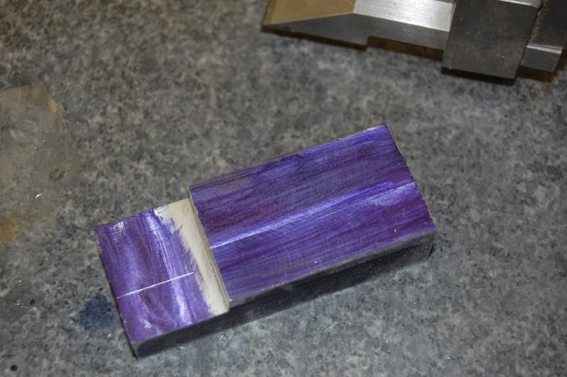
The slot was than cut using a 1/4" end mill and staying within the guidelines that were established.

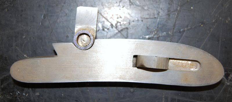
The forward part of the slot goes all the way through the plate; however, there is also a slot that goes only part of the way through the plate that is only visible from the inside. This is where the sear will fit in the finished lock.

The 1/4" cutter leaves a radius that must be removed from the finished slot. I suppose a broach would be ideal for this step, but I chose to do it with a handfile that had one face ground safe. The edges of the slot look a bit fuzzy in the photos, but they are actually pretty clean, I'll do a bit more work on the slot when the hammer is being made.

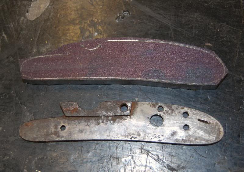
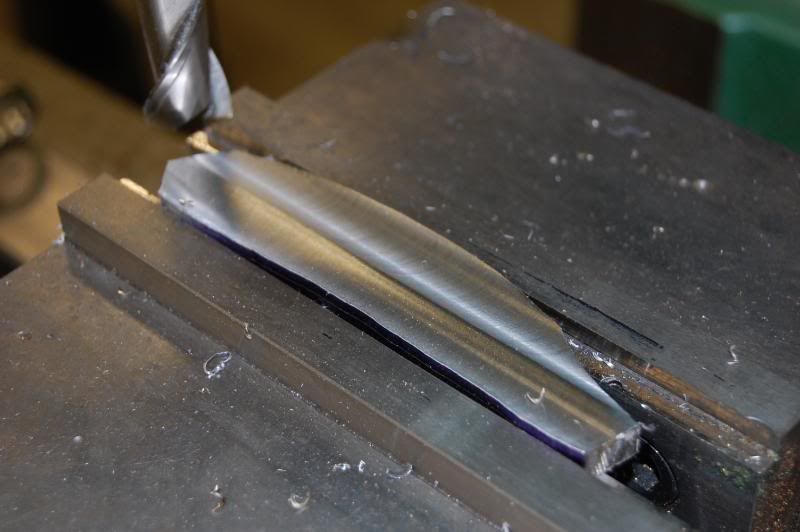
Following this step the plate was than filed and ground down to the outside guidelines established earlier. I set the table on my disk sander to 3 degrees to cut a slight draft on the plate to help with inletting in the future. Power tools are nice, but some jobs still need to be done by hand with a file which is what I used for the final finishing and shaping.
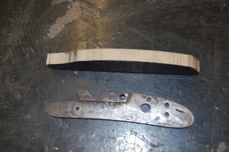
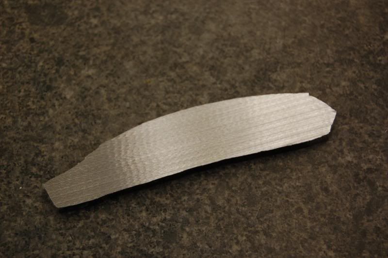
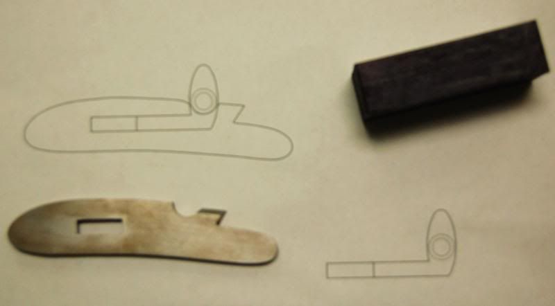
Here are a couple pictures of the plate as it is right now. The first photos were taken at a slight angle and the plate looks slightly different than the original, it is actually pretty close to the original shape; however, I will refine the forward part a bit more in the final finishing stage.

The hammer was attempted next. I thought initially about forging the hammer from thinner stock, but decided to go with a stock removal approach. I happened to have a chunk of 1 1/2" mild steel bar that was left over from a previous project and it seemed a likely candidate for this job. I will be using mild steel for everything on this lock except the springs and the screws which will be made out of 01 and 12L14 respectively. The mild steel will work fine for the main parts since I plan on color casehardening the lock after I've finished inletting it in the stock.
The following pictures show the original chunk of steel, the layout, and finally cutting it off on the bandsaw.


I suppose a hacksaw would work also, but I'm much too lazy for that approach and find the prospect of that much hacksawing depressing at best.
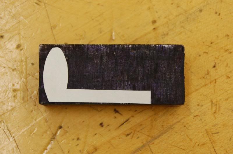
Though in many ways this lock build is a process of trial and error, I prefer to do most of my mistakes on paper (or CAD) and this is what I have done to determine the final size of the hammer and its relationship to the plate. It probably would have been easier to have left out the notch in the plate until after the hammer was finished, but I was trying to keep as close to the shape of the original lock as possible and did this first. Unfortunately, this made the final shape of the hammer more critical and difficult to do. The next few photos show the AutoCAD program I used to draw up the main elements and also a picture of a print that I produced. If anyone is interested I can provide the file in DXF format and it can be opened on another CAD program (ProgCAD is free and compatable with AutoCAD DXF)
Once the hammer size was determined a pattern was cut out of paper and will be used to scribe the rough layout lines on the hammer blank after it is trued up on the mill.
The blank is surfaced on both faces and the bottom edge in the following photos.

The exact location of the hammer nose is established using the CAD files for reference and transferring this information to the hammer blank using a digital height gage on a surface plate.
I decided to use a rotary table to cut the hammer nose. There would certainly be other ways that this could be done, but the table was handy and already mounted on one of the other mills so I figured why not. I'll be the first to admit that I'm not a big fan of setting these things up and the next photo demonstrates part of the process. The table must be aligned with the spindle center before this step can be done. I used a headstock center and an edge finder to locate the true center.
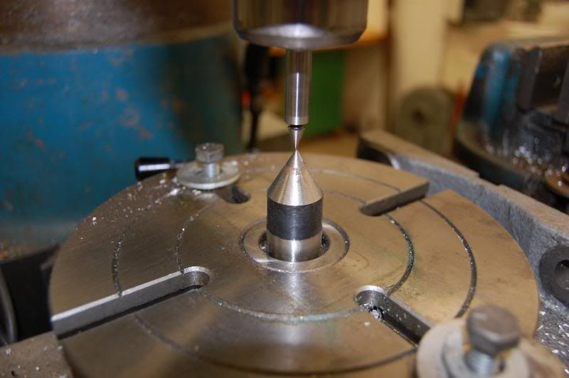
The center point scribed on the hammer was carefully aligned with the center/edgefinder in the mill and clamped to the table. Following this the hammer nose was milled in.
Once this was accomplished the profile was further roughed out on the mill.

As you can see in the above photos there is still lots of material to be removed by filing/grinding to get at the finished shape.
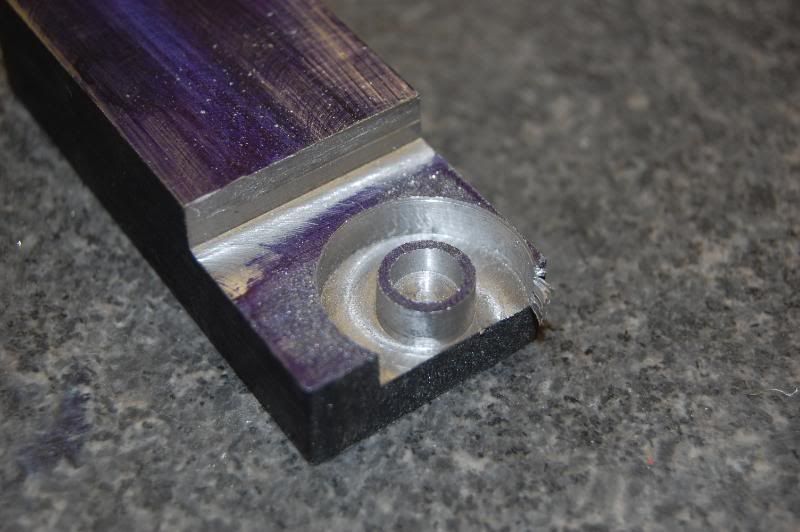
Next the radius on the tumbler end was established using the slot in the plate as a guide. A suitable washer was found in the scrap bin and used to scribe the radius on the hammer blank.
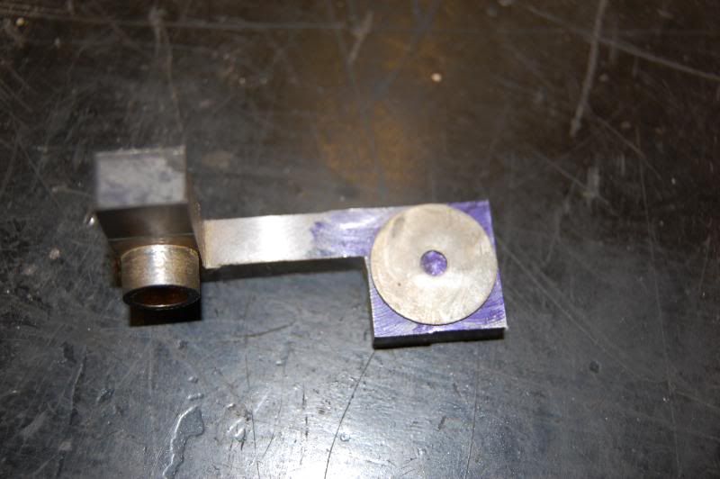
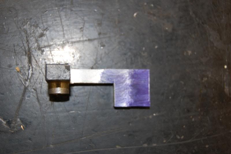
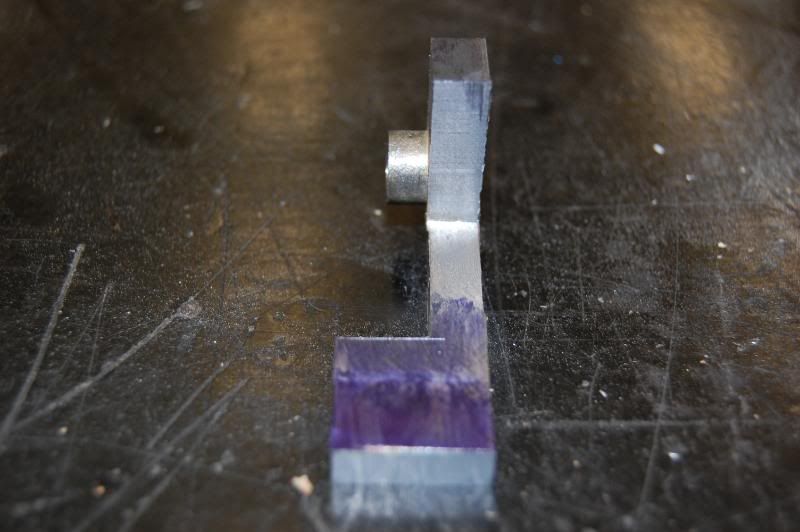
After grinding in the radius I checked the fit of the hammer to the plate.
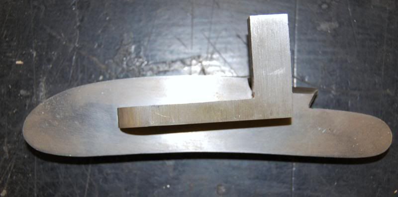

Here is a picture after it was cleaned up a bit and the nose of the hammer was also worked on a bit, though a considerable amount of shaping remains to be done. Still, I think it is looking like a Mule Ear.

My next major task is to make the sear and cut the notches in the tumbler end of the hammer. These shouldn't be too much of a problem, the spring might be my biggest headache because it is going to have to make a horizontal bend to clear the barrel. I think I have it worked out, but I guess I'll find out when I get to that stage. So far its been fun and my son has been able to spend some time in the shop with me lately and this will eventually be a rifle I build for him so I guess we'll just see where it goes. Thanks for looking.